Wiring Options
Over 50 Years of Experience
Complimentary Application Assistance and Engineering Design Support
No Charge Prototypes
Wiring Options for Strip-Switch™ and Bump-Switch™ Products
Switches and Sensors Inc's Strip-Switches and Bump-Switches are available with either 2- or 4-wire electrical connections. The 2-wire style is standard and suitable for most applications. The 4-wire style is optional and used where circuit monitoring is appropriate. If you have any questions about wiring your new switches or would like a free estimate, please fill out our online form or give us a call.
In many cases, the switch can be connected directly in series with the load. If the current or voltage of the load exceeds the switch specifications, the load should be isolated. This can be accomplished with either the 2-wire or 4-wire configuration. Typical circuit arrangements are shown below:

Above: The most common method of wiring. When the switch is closed, the relay is energized.

Above: The relay coil is normally energized in this configuration. If any of the following conditions occur, the relay coil will de-energize:
- Switch closure (short relay coil)
- Any open in the circuit (interrupts current to relay coil)
- Any short in the circuits (shorts relay coil)

Above: In this configuration, a set current normally flows through the resistor, generating a voltage (Vm) which is monitored by a voltage-sensing device. If any of the following conditions occur, the voltage across the resistor will drop to zero and activate the sensing device.
- Switch closure (no voltage across resistor)
- Any open in the circuit (no current flow to resistor)
- Any short in the circuit (no voltage across resistor)
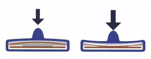
Switch Operation
- When a load is applied to the rib, it causes the top conductor to be deflected toward the lower conductor.
- When the upper conductor is deflected enough to touch the lower conductor, the switch is activated.
- When the load is removed, the upper conductor breaks contact with the lower conductor.
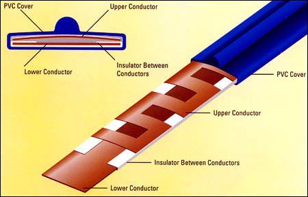
Linear Switching Elements
Strip-Switch™ linear switching elements are normally open, momentary-contact, pressure-activated switches. They are available in lengths ranging from 2 inches to 2,000 feet.
The conductors are made from a precisely formulated alloy that has very low resistance. It is then specially processed to produce a highly consistent switching action, together with an extremely long mechanical life expectancy.
Strip-Switch™ products are designed for more than 5 million operations at any given point.
Learn More About
Switches and Sensors Inc

Share On: